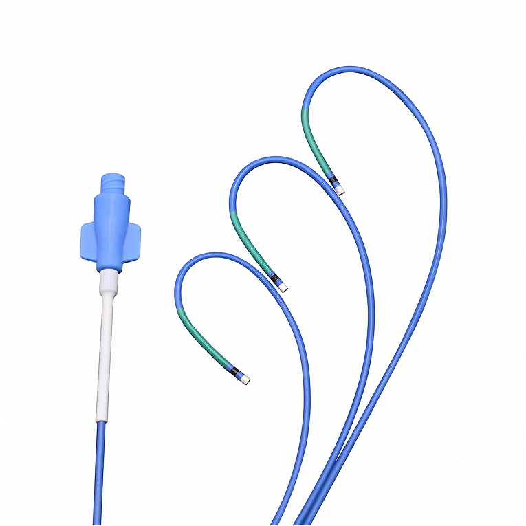
An ultra-thin wall and large lumen let complex devices pass, and multi-durometer design keeps the tip soft while the shaft pushes. The PTFE inner layer lets guidewires and high-viscosity contrast media move smoothly.
Catalogue curves cover XB 3.0 · 3.5 · 4.0, JL3–JL5, JR3–JR5, AL 0.75 · 1 · 2 · 3, AR · AR1 · AR2, MPA2, XBRCA and ABU 2.0–5.0. For curves not listed, send a drawing and we confirm whether the shape can be formed.
Guidewires and high-viscosity contrast media pass without catching. Sections that need bonding are etched to improve adhesion.
Carries torque transmission and shape retention. Carrier count and braid angle are tuned to the stiffness you need.
Stiff proximally, soft distally, divided by segment. The tip is formed as a soft tip that reduces vessel trauma.
Standard outer diameters are 5F 1.80 mm, 6F 2.10 mm, 7F 2.40 mm and 8F 2.65 mm. Inner diameter varies with the wall build even at the same Fr.
Yes. Send a drawing or a physical sample and we come back on mold feasibility and schedule.
Yes. We supply the shaft on its own, or as a finished device assembled with hub and strain relief.
We handle EO sterilization and individual packaging. Tell us the specification you need with your inquiry.
Size (Fr), curve, working length. Those three are enough to start. A drawing makes it faster.